Gauss gun. Scientific research work of students of class 9 "A" Kurichin Oleg and Kozlov Konstantin.
 Gauss gun is the most common name for a device whose operating principle is based on the use of a powerful electromagnet to accelerate objects. Typically, an electromagnet consists of a ferromagnetic core on which a wire is wound (hereinafter referred to as the winding). When current passes through the winding, a magnetic field is generated.
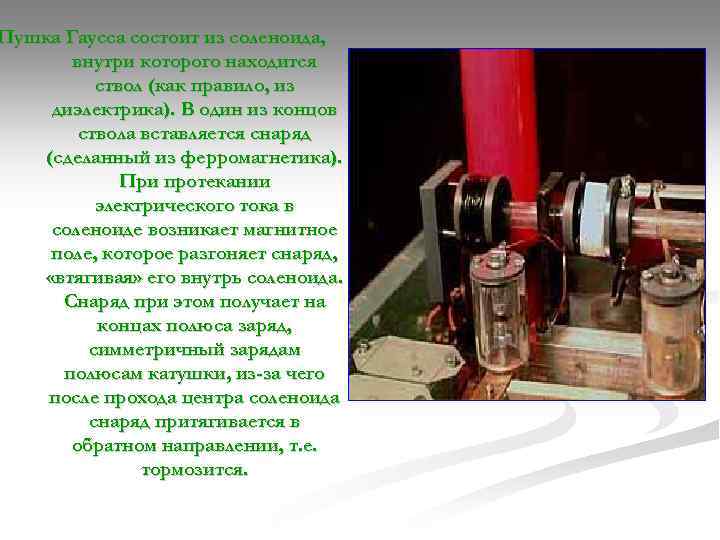 The Gauss gun consists of a solenoid, inside of which there is a barrel (usually made of dielectric). A projectile (made of a ferromagnetic material) is inserted into one end of the barrel. When an electric current flows in the solenoid, a magnetic field arises, which accelerates the projectile, “pulling” it into the solenoid. In this case, the projectile receives a charge at the ends of the pole that is symmetrical to the charges at the poles of the coil, which is why, after passing through the center of the solenoid, the projectile is attracted in the opposite direction, i.e., it is slowed down.
 But if, at the moment the projectile passes through the middle of the solenoid, the current in it is turned off, the magnetic field will disappear, and the projectile will fly out of the other end of the barrel. When the power source is turned off, a self-induction current is formed in the coil, which has the opposite direction of the current, and therefore changes the polarity of the coil.
 This means that when the power source is abruptly turned off, a projectile flying past the center of the coil will be repelled and accelerated further. Otherwise, if the projectile has not reached the center, it will decelerate. For the greatest effect, the current pulse in the solenoid must be short-term and powerful.
 As a rule, electrical capacitors with high operating voltage are used to obtain such a pulse. The parameters of the winding, projectile and capacitors must be coordinated in such a way that when fired, by the time the projectile approaches the middle of the winding, the current in the latter would have already decreased to a minimum value (that is, the charge of the capacitors would have already been completely consumed). In this case, the efficiency of a single-stage Gauss gun will be maximum.
 Units with only one coil are generally not very efficient. In order to achieve a really high speed of projectile flight, it is necessary to assemble a system in which the coils will turn on one by one, drawing the projectile into themselves, and automatically turn off when it reaches the middle of the coil. The figure shows a version of such an installation with several coils.
 The Gauss gun as a weapon has advantages that other types do not have small arms. This is the absence of cartridges and unlimited choice of the initial speed and energy of the ammunition, as well as the rate of fire of the gun, the possibility of a silent shot (if the projectile speed does not exceed the speed of sound), including without changing the barrel and ammunition, relatively low recoil (equal to the impulse of the ejected projectile, there is no additional impulse from powder gases or moving parts), theoretically, greater reliability and wear resistance, as well as the ability to work in any conditions, including outer space.
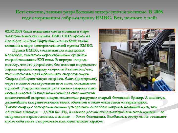 Naturally, the military is interested in such developments. In 2008, the Americans assembled the EMRG gun. Here's a little about it: 02. 2008 the world's most powerful electromagnetic gun was tested. The US Navy tested the world's most powerful electromagnetic gun, EMRG, at a test site in Virginia. The EMRG gun, created for surface ships, is considered a promising weapon of the second half of the 21st century. First of all, because this device, without the help of a powder charge, gives the projectile a speed of 9 thousand km/h, which is several times the speed of sound. The projectile gains such speed due to its flight through the powerful electromagnetic field created by the gun. Destructive force of such a projectile is also very high. During the tests, due to the high kinetic energy, the projectile completely destroyed the old concrete bunker. This means that in the future, explosives can be abandoned to destroy such objects. Also, a projectile with electromagnetic acceleration is capable of covering a longer distance than conventional projectiles - up to 500 km. Well, the main advantage of an electromagnetic gun is that its projectiles are not explosive, which means they are safer. In addition to this, it does not leave behind cartridges with a powder or chemical charge.
 However, not only the American military assembles Gauss guns. Not long ago Alan Parek built his own setup. It took him 40 hours and 100 euros to create it. The gun weighs 5 kg, is designed for 14 shots and has a semi-automatic firing mode. Here is a photo of this installation.
 However, despite the apparent simplicity of the Gauss gun and its advantages, using it as a weapon is fraught with serious difficulties. The first difficulty is the low efficiency of the installation. Only 1-7% of the capacitor charge is converted into the kinetic energy of the projectile. This disadvantage can be partially compensated for by using a multi-stage projectile acceleration system, but in any case, the efficiency rarely reaches even 27%. Therefore, the Gauss gun is inferior in terms of shot force even to pneumatic weapons. The second difficulty is high energy consumption (due to low efficiency) and sufficient long time recharging capacitors, which forces a power source (usually a powerful battery) to be carried along with the Gauss gun. Efficiency can be significantly increased by using superconducting solenoids, but this will require a powerful cooling system, which will significantly reduce the mobility of the Gauss gun. The third difficulty follows from the first two. This heavy weight and dimensions of the installation, with its low efficiency.
 We also assembled a similar installation using a glass tube about 1 m long, an inductor with 100 turns and 3 capacitors, each with a capacity of 58 microns. F (all this was found in the physics classroom).

 We collected various mounting options and tried to determine which projectile shape would be most suitable for shooting. L of projectile 1 cm 2 cm 3 cm 4 cm L of shot 1. 5 m 3. 14 m 3. 2 m m D of projectile 1 cm 0.5 cm 1 mm L of shot 1. 87 m 2. 87 m 3. 21 m 2 , 5 m Table 2. The length of the projectile changes (the thickness is constant). 0.5 mm Table 3. The thickness of the projectile changes (length L = 3 cm, the best from previous experience).
 Our second goal was to find out what number of turns in the installation coil and what capacitor capacity would allow the projectile to fly best. 174 100000 C 58 116 μm condensate μm μm μ. F F ra F F L shot 0.9 m 1.7 m 3.1 m 0.6 m N turns 0.2 m 100 pcs L shot 3. 07 m 200 pcs 300 pcs 400 pcs 2. 84 m 2. 7 m 2. 56 m
 Nai best characteristics projectile and installation in the previous You can notice that the best characteristics in the tables were highlighted in red. are in the “middle”, between the largest and most U 40 to 80 to 160 to 220 to small values. conden It's pretty easy to explain. satator The time for complete discharge of the capacitor is equal to one quarter of the period. Consequently, having a large capacity, the capacitor will L 1 m 1. 7 m 3. 3 m 3. 21 m take a long time to discharge. As a result, we will get a short range of the projectile. la Also, an installation with a low capacitor voltage as a result has a large capacity, which, as mentioned above, affects the projectile’s flight range. .
 As can be seen from the table, the length of the barrel does not play a special role here. L of the projectile 1.7 cm 0.5 m 1 m L of the shot 3.01 m 2.98 m 3.08 m Still, one of the goals of our research was achieved - we found out what characteristics of the coil and the projectile will allow the latter to fly the farthest . As already mentioned, this is a capacitor capacity of 174 microns. F, barrel length 1 m and 100 turns in the coil. We took the voltage of the capacitors to be 220 V. The nail used as a projectile is about 1 mm in diameter and 3 cm in length.
 After all the research, we realized the following: The possibility of the existence of a Gauss gun has been proven, which means the goal of the research has been achieved.
Presentation to research work"Gauss gun". Study of the operating principle of a Gauss gun, an electromagnetic mass accelerator, operating on the phenomenon of electromagnetic induction.
View document contents
"Annotation"
Annotation.
The device - “Gauss Gun” refers to an electromagnetic mass accelerator, which operates on the phenomenon of electromagnetic induction.
Goal of the work: study of the operating principle of an electromagnetic mass accelerator based on a Gauss gun and the possibility of its application in electrical engineering.
Tasks:
1. Study the structure of the Gauss gun and build its experimental model
2. Consider the parameters of the experiment
3. Research the issue practical application devices operating on the principle of a Gauss gun
Research methods: experiment and modeling.
The experimental setup consists from the charging unit and oscillatory circuit.
The charger is powered by 220V AC mains, 50Hz, and consists of four semiconductor diodes. The oscillatory circuit includes: a capacitor with a capacity of 800 μF and 330 V, an inductor of 1.34 mH.
A horizontal shot was fired from a prototype with a mass of m = 2.45 g, while the flight range was on average s = 17 m, with a flight altitude h = 1.20 m.
Based on the initial experimental data: the masses of two projectiles, voltage, capacitor capacity, flight range and altitude, I calculated the energy stored by the capacitor, flight time, speed, kinetic energy of projectile movement, and installation efficiency.
| Original data |
||
| Flight range, s | ||
| Flight altitude, h | ||
| Capacitor capacity, C | ||
| Mains voltage, U | ||
| Experimental data | ||
| Energy stored in the capacitor, E c = | ||
| Capacitor discharge time, T times = | ||
| Solenoid inductance, L = | ||
| Flight time, t = | 0.4 9 s | |
| Projectile departure speed, 𝑣 = | ||
| Projectile kinetic energy, E = | ||
| Gun efficiency | ||
Conclusions: I managed to collect operating installation accelerator with efficiency = 3.2% - 4.6%. The model was examined by me for the range of the projectile. I established the dependence of the flight range on the projectile departure speed and calculated the efficiency of the installation. To increase efficiency it is necessary
A. increase the speed of projectile departure, because the faster the projectile moves, the less
losses during its acceleration. This can be achieved by
1. reducing the mass of the projectile. My experimental studies showed that a projectile weighing 2.45 g has a flight range of 11 m and an exit speed of 22.45 m/s; projectile - 1.02g - 20.5m and 41.83m/s;
increasing the power of the magnetic field by increasing the inductance of the coil. To do this, I increased the number of turns, which, accordingly, with a constant wire diameter, increased the diameter of the coil itself;
time limits on the action of a magnetic field on a projectile. To do this, the solenoid must be taken short.
B. The shorter and thicker the connecting wires, the more efficient Gauss will be.
C. It is very promising to make a multi-stage magnetic accelerator - each subsequent stage will have a higher efficiency than the previous one due to the increase in projectile speed. But when the projectile remains in the zone of effective action of the accelerating magnetic field for a short time, it is necessary to establish a current of the required value in the solenoid as quickly as possible, and then turn it off in order to avoid wasteful waste of energy. All this is hampered by the inductance of the coil and the requirements for the parameters of switching devices. There are many ways to solve this problem different ways- use subsequent windings of increasing length with a constant number of turns - the inductance will be lower, and the time of flight of the projectile through them will not be much longer than that of the previous stage. To make an effective multi-stage magnetic mass accelerator, which is not particularly critical to its settings, it is necessary to provide several important conditions:
use one common power source for the windings;
use switches that ensure strictly timed switching on of current to the winding;
use synchronous switching on and off with the movement of the projectile
windings - the current in the winding must turn on when the projectile enters the zone
effective action of the accelerating magnetic field, and must turn off,
when the projectile leaves this zone;
Use different windings at different stages.
View presentation content
"Gauss Gun"

Gauss gun
(English: Gauss gun, Coil gun, Gauss cannon) - one of the types of electromagnetic mass accelerator.
The gun is named after the German scientist Carl Gauss, who laid the foundations mathematical theory electromagnetism.
Vanyushin Semyon,
9th grade student of Municipal Educational Institution “Secondary School No. 56”, Cheboksary


Discovery Channel Photos
http://www.coilgun.info/discovery/photos.htm

Part name
In the 1st gun
Number of layers
in the 2nd gun
Solenoid length
Number of turns
Material
Diameter, shape
Length
Streamlined, cylindrical
Weight


Initial data
Flight range, s
Flight altitude, h
Capacitor capacity, C
Mains voltage, U
Experimental data
Energy stored in the capacitor, E
Capacitor discharge time, T times
Operating time of the inductor, T
Solenoid inductance, L
Flight time, t
Projectile departure speed,𝑣
Projectile kinetic energy, E

Advantages:
Flaws:
lack of cartridges
high energy consumption
unlimited choice of initial speed and ammunition energy.
low efficiency of the installation (the Gauss gun is inferior in shot force even to pneumatic weapons)
the possibility of a silent shot without changing the barrel and ammunition.
large weight and dimensions of the installation, with its low efficiency
relatively low return.
greater reliability and wear resistance.
ability to work in any conditions, including in outer space.

- On this moment The Gauss gun is used only as a toy or various tests are carried out with it. Thus, in February 2008, the US Navy installed a railgun on a destroyer as a ship's weapon, accelerating a projectile to 2520 m/s. Laboratory installations for studying high-speed impact send particles weighing less than 1 g at a target at speeds of up to 15 km/s.


Principle of operation.
http://upload.wikimedia.org/wikipedia/commons/f/f7/Coilgun_animation.gif

Project
Gauss gun.
Electromagnetic mass accelerator (EMUM)
Completed by 9th grade students
GBOU Secondary School 717, Northern Administrative District, Moscow
Polyakova Marina
Litvinenko Ruslan
Project leader, physics teacher:
Dmitrieva Olga Alexandrovna
MOSCOW, 2012
INTRODUCTION……………………………………………………..3
CHAPTER I OPERATING PRINCIPLE (GENERAL)…………………………5
NECESSARY FORMULAS FOR CALCULATION……………………..7
ALGORITHM AND DESCRIPTION OF MODEL ASSEMBLY………………….8
USAGE SCHEME……………………………………………………11
PRINCIPLE OF THE CREATED MODEL……………………….…...…11
CHAPTERII APPLICATION OF THIS DEVICE……………....13
2.1 IN SPACE AND PEACEFUL PURPOSES………………………………….14
2.2 FOR MILITARY PURPOSES…………………………………………………………….15
2.3 OUR PROPOSAL.………………………………………………………..16
CONCLUSION……………………………………………………………..18
LITERATURE……………………………………………...………….21
APPLICATION
INTRODUCTION
The principle of the device was developed by Carl Gauss, a German physicist, astronomer and mathematician.
The project is dedicated to an invention called the Gauss Gun (Gauss Gun or Coil Gun, as it is called in the Western style), named after the outstanding German mathematician, astronomer and physicist
XIX century, who formulated the basic principles of the operation of weapons based on electromagnetic acceleration of masses, Gauss Gun.
Many people have heard about the Gauss cannon from science fiction books or computer games, since the Gauss Cannon is very popular in science fiction, where it acts as a personal
high-precision lethal weapons, as well as stationary high-precision and high-rate weapons.
Among the games, the Gauss cannon appeared in Fallout 2, Fallout Tactics, Half-life (there is an experimental weapon called the Tau cannon), and in StarCraft, infantrymen are armed with a C-14 "Impaler" automatic Gauss rifle. Also, a weapon similar to a Gauss cannon appeared in the Quake series of games, but in the minds of many this gun remains simply an invention of science fiction writers, which at best has high-sized prototypes in reality.
Goal of the work: study the structure of an electromagnetic mass accelerator (Gauss gun), as well as the principles of its operation and application. Build a working model of the Gauss Cannon.
Main goals:
Examine the device using drawings and layouts.
Study the structure and operating principle of an electromagnetic mass accelerator.
Create a working model.
Application of this model.
Practical part of the work:
Creation of a functioning model of a mass accelerator in a school setting. Computer presentation of the project in Power Point format.
Hypothesis: Is it possible to create the simplest functioning model of a Gauss Cannon in a school environment?
Relevance of the project: this project is interdisciplinary and covers a large number of material.
1This article is an abstract presentation of the main work. Full text scientific work, applications, illustrations and other additional materials are available on the website of the II International Competition of Scientific Research and creative works students “Start in Science” at the link: https://www.school-science.ru/2017/11/26807.
My interest in reconstructing the Gauss gun is caused by the ease of assembly and availability of materials, ease of use on the one hand and high energy consumption on the other, which determined the main problem of the research. The spectrum of application of an electromagnetic accelerator in Everyday life. Create a model of a mass accelerator, based on the analysis of experimental data, find out where a Gauss gun can be used, in what areas of human life.
These contradictions actualized and determined the choice of the research topic: “Gauss gun - a weapon or a toy?”
Why did I choose this topic? I became interested in the design of the gun and decided to create a model of such a Gauss gun, i.e. amateur installation. It can be used as a toy. But while creating the model, I began to think about where else the Gauss gun could be used and how to design a more powerful gun, what is needed for this?! How can you increase the traveling electromagnetic field?
Purpose of the work: To create and explore various design options for the Gauss gun when changing the physical parameters of the gun parts.
Research objectives:
1. Create a working model of a Gauss gun to demonstrate the phenomenon of electromagnetic induction in physics lessons.
2. Investigate the efficiency of the Gauss gun from the capacitance of the capacitor and the inductance of the solenoid.
3. Based on the research results, propose new areas of application of the gun in the field of human life support.
The subject of the study is the phenomenon of electromagnetic induction.
The object of study is the Gaussian Gun model.
Research methods:
1. Analysis of scientific literature.
2. Material modeling, design.
3. Experimental methods research
4. Analysis, generalization, deduction, induction.
Practical significance: This device can be used for demonstration in physics lessons, which will contribute to students’ better understanding of these physical phenomena.
Gauss gun (eng. Gaussgun, Coilgun, Gausscannon) is one of the types of electromagnetic mass accelerator.
Named after the German scientist Carl Gauss, who laid the foundations of the mathematical theory of electromagnetism. It should be borne in mind that this method of mass acceleration is used mainly in amateur installations, since it is not effective enough for practical implementation. Its operating principle (creation of a traveling magnetic field) is similar to a device known as a linear motor.
Operating principle of a Gauss gun
The Gauss gun consists of a solenoid, inside of which there is a barrel (usually made of dielectric). A projectile (made of a ferromagnetic material) is inserted into one end of the barrel. When an electric current flows in the solenoid, a magnetic field arises, which accelerates the projectile, “pulling” it into the solenoid. In this case, poles are formed at the ends of the projectile, oriented according to the poles of the coil, due to which, after passing the center of the solenoid, the projectile is attracted in the opposite direction, that is, it is slowed down. In amateur circuits, a permanent magnet is sometimes used as a projectile since it is easier to combat the induced emf that arises. The same effect occurs when using ferromagnets, but it is not so pronounced due to the fact that the projectile is easily remagnetized (coercive force).
For the greatest effect, the current pulse in the solenoid must be short-term and powerful. As a rule, electrolytic capacitors with a high operating voltage are used to obtain such a pulse.
The parameters of the accelerating coils, projectile and capacitors must be coordinated in such a way that when a shot is fired, by the time the projectile approaches the solenoid, the magnetic field induction in the solenoid is maximum, but with further approach of the projectile it drops sharply. It is worth noting that different algorithms for the operation of accelerating coils are possible.
Creation and debugging of the Gauss Cannon
The simplest structures can be assembled from scrap materials even with school knowledge of physics.
Let's start assembling the gun with a solenoid (an inductor without a core). The barrel of the coil is a piece of plastic straw 40 cm long. We carefully wind a copper wire around it, turn to turn - the firing range of our gun will depend on the quality of the assembly. In total you need to wind 9 layers. In practice, I have found that it is better to wind two layers of the excitation winding with a conductor in polyvinyl chloride insulation, which in this case should not be too thick (no more than 1.5 mm in diameter). Then you can disassemble everything, remove the washers and put the reel on the felt-tip pen rod, which will serve as the barrel. The finished coil can be easily tested by connecting it to a 9-volt battery: it acts as an electromagnet. The parameters of the winding, projectile and capacitors must be coordinated in such a way that when fired, by the time the projectile approaches the middle of the winding, the current in the latter would have already decreased to a minimum value, that is, the charge of the capacitors would have already been completely consumed. In this case, the efficiency of a single-stage Gauss gun will be maximum. Next, we assemble the electrical circuit and fix its elements on a fixed stand. You can give the cannon the shape of a pistol by placing the chain parts in the body of a plastic children's toy. But I placed the chain in the body of a cardboard box.
In accordance with the described technology, I created two working models. I spent parallel experiment, accordingly changing the system of capacitors (in the second model there are several capacitors, in the first - one), the number of turns of the solenoid, various types of connection of circuit sections.
When researching the gun, I came to the conclusion that the materials for assembling the installation are available; there is a lot of literature in the world that helps to understand the principles of the gun’s operation and various ways its assemblies. But when using a gun, the problem of using it arises, which is modern world the gun can only be used for military and space purposes, because It is very difficult to calculate the behavior of the coil when using models in other sectors of human activity.
I found out that it is theoretically possible to use Gauss guns to launch light satellites into orbit. The main application is amateur installations, demonstration of the properties of ferromagnets. It is also quite actively used as a children's toy or for developing technical creativity. homemade installation(simplicity and relative safety).
However, despite the apparent simplicity of the Gauss cannon, using it as a weapon is fraught with serious difficulties, the main one of which is high energy consumption.
The first and main difficulty is the low efficiency of the installation. Only 1-7% of the capacitor charge is converted into the kinetic energy of the projectile. This disadvantage can be partially compensated for by using a multi-stage projectile acceleration system, but in any case, the efficiency rarely reaches 27%. Basically, in amateur installations, the energy stored in the form of a magnetic field is not used in any way, but is the reason for the use of powerful switches to open the coil (Lenz's rule).
The second difficulty is high energy consumption (due to low efficiency).
The third difficulty (follows from the first two) is the large weight and dimensions of the installation with its low efficiency.
The fourth difficulty is the rather long cumulative recharging time of the capacitors, which makes it necessary to carry a power source (usually a powerful battery) along with the Gauss gun, as well as their high cost. It is theoretically possible to increase efficiency by using superconducting solenoids, but this will require a powerful cooling system, which brings additional problems and seriously affects the field of application of the installation. Or use battery-replaceable capacitors.
The fifth difficulty is that with an increase in the speed of the projectile, the time of action of the magnetic field during the passage of the solenoid by the projectile is significantly reduced, which leads to the need not only to turn on each subsequent coil of the multi-stage system in advance, but also to increase the power of its field in proportion to the reduction of this time. Usually this drawback is immediately overlooked, since most homemade systems have either a small number of coils or insufficient bullet speed.
In conditions aquatic environment the use of a gun without a protective casing is also seriously limited - remote current induction is sufficient for the salt solution to dissociate on the casing with the formation of aggressive (solvent) environments, which requires additional magnetic shielding.
Thus, today the Gauss cannon has no prospects as a weapon, since it is significantly inferior to other types of small arms that operate on different principles. Theoretically, prospects are, of course, possible if compact and powerful sources of electric current and high-temperature superconductors (200-300K) are created. However, an installation similar to a Gauss gun can be used in outer space, since in conditions of vacuum and weightlessness many of the disadvantages of such installations are leveled out. In particular, the military programs of the USSR and the USA considered the possibility of using installations similar to the Gauss gun on orbiting satellites to defeat others spacecraft(shells with a large number of small damaging parts), or objects on the earth's surface.
Tests of the Gauss gun gave a figure of 27% efficiency. That is, according to experts, a gauss shot is inferior even to Chinese pneumatics. Reloading is slow - the rate of fire is out of the question. And the biggest problem is that there are no powerful, mobile energy sources. And until these sources are found, we can forget about armament with gauss guns.
Bibliographic link
Beketov K.S. GAUSS CANNON – WEAPON OR TOY? // International school scientific bulletin. – 2016. – No. 3. – P. 45-47;URL: http://school-herald.ru/ru/article/view?id=74 (date of access: 08/24/2019).
The project was started in 2011. It was a project involving a fully autonomous automatic system for entertainment purposes, with a projectile energy of about 6-7 J, which is comparable to pneumatics. It was planned to have 3 automatic stages with launch from optical sensors, plus a powerful injector-impactor that fires a projectile from the magazine into the barrel.
The layout was planned as follows:
That is, a classic Bullpup, which made it possible to move heavy batteries into the butt and thereby shift the center of gravity closer to the handle.
The diagram looks like this:
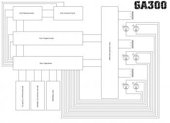
The control unit was subsequently divided into a power unit control unit and a general management. The capacitor block and switching block were combined into one. Backup systems were also developed. From these, a control unit for the power unit, a power unit, a converter, a voltage distributor, and part of the display unit were assembled.
It consists of 3 comparators with optical sensors.

Each sensor has its own comparator. This was done to increase reliability, so if one microcircuit fails, only one stage will fail, and not 2. When the projectile blocks the sensor beam, the resistance of the phototransistor changes and the comparator is triggered. With classical thyristor switching, the control terminals of the thyristors can be connected directly to the outputs of the comparators.
The sensors must be installed as follows:

And the device looks like this:

The power block has the following simple circuit:

Capacitors C1-C4 have a voltage of 450V and a capacity of 560uF. Diodes VD1-VD5 are used type HER307/ Power thyristors VT1-VT4 type 70TPS12 are used as switching.

The assembled unit connected to the control unit in the photo below:

The converter was low-voltage, you can find out more about it
The voltage distribution unit is implemented by a banal capacitor filter with a power switch and an indicator notifying the process of charging the batteries. The block has 2 outputs - the first is power, the second is for everything else. It also has terminals for connecting a charger.

In the photo the distribution block is on the far right at the top:

In the lower left corner there is a backup converter; it was assembled according to the simplest circuit using NE555 and IRL3705 and has a power of about 40W. It was supposed to be used with a separate small battery, including a backup system in case of failure of the main battery or discharge of the main battery.
Using a backup converter, preliminary checks of the coils were carried out and the possibility of using lead batteries was checked. The video shows a single-stage model shooting at a pine board. A bullet with a special tip of increased penetration capacity enters the tree 5mm.
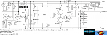
Within the project, a universal stage was also developed as the main block for subsequent projects.
This circuit is a block for an electromagnetic accelerator, on the basis of which it is possible to assemble a multi-stage accelerator with a number of stages up to 20. The stage has a classic thyristor switching and an optical sensor. The energy pumped into the capacitors is 100J. Efficiency is about 2 percent.

A 70W converter with a master oscillator based on the NE555 chip and an IRL3705 power field-effect transistor was used. Between the transistor and the output of the microcircuit, a repeater is provided on a complementary pair of transistors, which is necessary to reduce the load on the microcircuit. The comparator of the optical sensor is assembled on the LM358 chip; it controls the thyristor by connecting capacitors to the winding when the projectile passes the sensor. Good snubber circuits are used in parallel with the transformer and the accelerating coil.
Methods for increasing efficiency
Methods for increasing efficiency were also considered, such as magnetic circuits, coil cooling and energy recovery. I’ll tell you more about the latter.
GaussGan has a very low efficiency; people working in this area have long been looking for ways to increase efficiency. One of these methods is recovery. Its essence is to return unused energy in the coil back to the capacitors. Thus, the energy of the induced reverse pulse does not go anywhere and does not catch the projectile with a residual magnetic field, but is pumped back into the capacitors. This method can return up to 30 percent of the energy, which in turn will increase efficiency by 3-4 percent and reduce reload time, increasing the rate of fire in automatic systems. And so - the diagram using the example of a three-stage accelerator.

For galvanic isolation in the thyristor control circuit, transformers T1-T3 are used. Let's consider the operation of one stage. We apply the charging voltage to the capacitors, through VD1, capacitor C1 is charged to the nominal voltage, the gun is ready to fire. When a pulse is applied to input IN1, it is transformed by transformer T1 and goes to the control terminals VT1 and VT2. VT1 and VT2 open and connect coil L1 to capacitor C1. The graph below shows the processes during the shot.

We are most interested in the part starting at 0.40ms, when the voltage becomes negative. It is this voltage that can be caught and returned to the capacitors using recuperation. When the voltage becomes negative, it passes through VD4 and VD7 and is pumped into the next stage accumulator. This process also cuts off part of the magnetic pulse, which allows you to get rid of the inhibitory residual effect. The remaining stages work similarly to the first.
Project status
The project and my developments in this direction were generally suspended. Probably in the near future I will continue my work in this area, but I don’t promise anything.
List of radioelements
| Designation | Type | Denomination | Quantity | Note | Shop | My notepad | |
|---|---|---|---|---|---|---|---|
| Power section control unit | |||||||
| Operational amplifier | LM358 | 3 | To notepad | ||||
| Linear regulator | 1 | To notepad | |||||
| Phototransistor | SFH309 | 3 | To notepad | ||||
| Light-emitting diode | SFH409 | 3 | To notepad | ||||
| Capacitor | 100 µF | 2 | To notepad | ||||
| Resistor | 470 Ohm | 3 | To notepad | ||||
| Resistor | 2.2 kOhm | 3 | To notepad | ||||
| Resistor | 3.5 kOhm | 3 | To notepad | ||||
| Resistor | 10 kOhm | 3 | To notepad | ||||
| Power block | |||||||
| VT1-VT4 | Thyristor | 70TPS12 | 4 | To notepad | |||
| VD1-VD5 | Rectifier diode | HER307 | 5 | To notepad | |||
| C1-C4 | Capacitor | 560 µF 450 V | 4 | To notepad | |||
| L1-L4 | Inductor | 4 | To notepad | ||||
LM555 | 1 | To notepad | |||||
| Linear regulator | L78S15CV | 1 | To notepad | ||||
| Comparator | LM393 | 2 | To notepad | ||||
| Bipolar transistor | MPSA42 | 1 | To notepad | ||||
| Bipolar transistor | MPSA92 | 1 | To notepad | ||||
| MOSFET transistor | IRL2505 | 1 | To notepad | ||||
| Zener diode | BZX55C5V1 | 1 | To notepad | ||||
| Rectifier diode | HER207 | 2 | To notepad | ||||
| Rectifier diode | HER307 | 3 | To notepad | ||||
| Schottky diode | 1N5817 | 1 | To notepad | ||||
| Light-emitting diode | 2 | To notepad | |||||
| 470 µF | 2 | To notepad | |||||
| Electrolytic capacitor | 2200 µF | 1 | To notepad | ||||
| Electrolytic capacitor | 220 µF | 2 | To notepad | ||||
| Capacitor | 10 µF 450 V | 2 | To notepad | ||||
| Capacitor | 1 µF 630 V | 1 | To notepad | ||||
| Capacitor | 10 nF | 2 | To notepad | ||||
| Capacitor | 100 nF | 1 | To notepad | ||||
| Resistor | 10 MOhm | 1 | To notepad | ||||
| Resistor | 300 kOhm | 1 | To notepad | ||||
| Resistor | 15 kOhm | 1 | To notepad | ||||
| Resistor | 6.8 kOhm | 1 | To notepad | ||||
| Resistor | 2.4 kOhm | 1 | To notepad | ||||
| Resistor | 1 kOhm | 3 | To notepad | ||||
| Resistor | 100 Ohm | 1 | To notepad | ||||
| Resistor | 30 ohm | 2 | To notepad | ||||
| Resistor | 20 ohm | 1 | To notepad | ||||
| Resistor | 5 ohm | 2 | To notepad | ||||
| T1 | Transformer | 1 | To notepad | ||||
| Voltage distribution block | |||||||
| VD1, VD2 | Diode | 2 | To notepad | ||||
| Light-emitting diode | 1 | To notepad | |||||
| C1-C4 | Capacitor | 4 | To notepad | ||||
| R1 | Resistor | 10 ohm | 1 | To notepad | |||
| R2 | Resistor | 1 kOhm | 1 | To notepad | |||
| Switch | 1 | To notepad | |||||
| Battery | 1 | To notepad | |||||
| Programmable timer and oscillator | LM555 | 1 | To notepad | ||||
| Operational amplifier | LM358 | 1 | To notepad | ||||
| Linear regulator | LM7812 | 1 | To notepad | ||||
| Bipolar transistor | BC547 | 1 | To notepad | ||||
| Bipolar transistor | BC307 | 1 | To notepad | ||||
| MOSFET transistor | AUIRL3705N | 1 | To notepad | ||||
| Phototransistor | SFH309 | 1 | To notepad | ||||
| Thyristor | 25 A | 1 | To notepad | ||||
| Rectifier diode | HER207 | 3 | To notepad | ||||
| Diode | 20 A | 1 | To notepad | ||||
| Diode | 50 A | 1 | To notepad | ||||
| Light-emitting diode | SFH409 | 1 | |||||